Functions used by the ISR. More...
Functions | |
| void | confirmPolarity (const uint8_t phase) |
| Confirms the polarity of the current voltage sample for a specific phase. | |
| ISR (ADC_vect) | |
| Interrupt Service Routine - Interrupt-Driven Analog Conversion. | |
| uint8_t | nextLogicalLoadToBeAdded () |
| Retrieve the next logical load that could be added. | |
| uint8_t | nextLogicalLoadToBeRemoved () |
| Retrieve the next logical load that could be removed (in reverse order). | |
| void | proceedHighEnergyLevel () |
| Handles the case when the energy level is high, potentially adding a load. | |
| void | proceedLowEnergyLevel () |
| Handles the case when the energy level is low, potentially removing a load. | |
| void | processCurrentRawSample (const uint8_t phase, const int16_t rawSample) |
| Processes the current raw sample for the specified phase. | |
| void | processDataLogging () |
| Process data logging at the end of each logging period. | |
| void | processLatestContribution (const uint8_t phase) |
| Process the latest contribution after each phase-specific new cycle. | |
| void | processMinusHalfCycle (const uint8_t phase) |
| Processes the start of a new negative half cycle for the specified phase. | |
| void | processPlusHalfCycle (const uint8_t phase) |
| Process the start of a new positive half cycle for the specified phase. | |
| void | processPolarity (const uint8_t phase, const int16_t rawSample) |
| Processes the polarity of the current voltage sample for a specific phase. | |
| void | processRawSamples (const uint8_t phase) |
| Processes raw voltage and current samples for the specified phase. | |
| void | processStartNewCycle () |
| Processes the start of a new mains cycle on phase 0. | |
| void | processStartUp (const uint8_t phase) |
| Processes the startup period for the router. | |
| void | processVoltage (const uint8_t phase) |
| Processes the current voltage sample for the specified phase. | |
| void | processVoltageRawSample (const uint8_t phase, const int16_t rawSample) |
| Processes the current voltage raw sample for the specified phase. | |
| void | updatePhysicalLoadStates () |
| Updates the physical load states based on logical load priorities and states. | |
| void | updatePortsStates () |
| Updates the control ports for each of the physical loads. | |
Detailed Description
Functions used by the ISR.
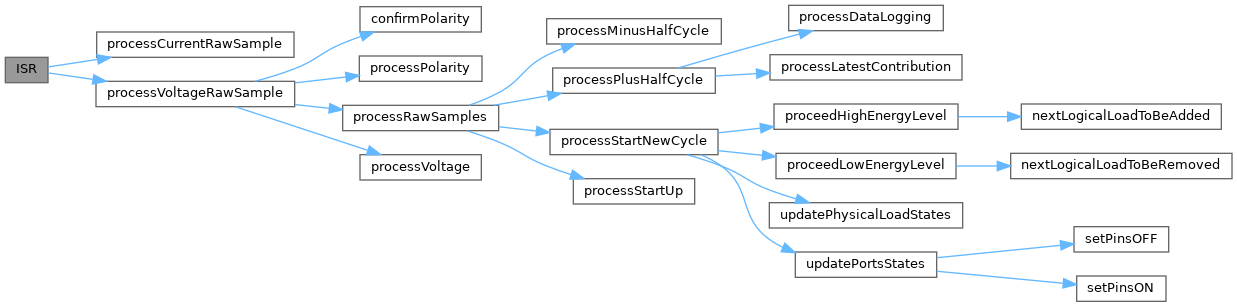
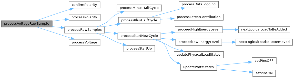
This group contains functions that are executed within the Interrupt Service Routine (ISR) or are closely tied to time-sensitive operations. These functions are optimized for speed and efficiency to ensure the system operates without delays or interruptions.
- Note
- These functions handle tasks such as ADC sampling, zero-crossing detection, and real-time data processing.
Function Documentation
◆ confirmPolarity()
|
inline |
Confirms the polarity of the current voltage sample for a specific phase.
This routine prevents a zero-crossing point from being declared until a certain number of consecutive samples in the 'other' half of the waveform have been encountered.
- Parameters
-
phase The phase number [0..NO_OF_PHASES[.
- If the polarity of the most recent sample matches the last confirmed polarity, the persistence counter is reset.
- If the polarity differs, the persistence counter is incremented.
- Once the persistence counter exceeds a predefined threshold, the polarity is confirmed.
Definition at line 469 of file processing.cpp.

◆ ISR()
| ISR | ( | ADC_vect | ) |
Interrupt Service Routine - Interrupt-Driven Analog Conversion.
An Interrupt Service Routine is now defined which instructs the ADC to perform a conversion for each of the voltage and current sensors in turn.
This Interrupt Service Routine is for use when the ADC is in the free-running mode. It is executed whenever an ADC conversion has finished, approx every 104 µs. In free-running mode, the ADC has already started its next conversion by the time that the ISR is executed. The ISR therefore needs to "look ahead".
At the end of conversion Type N, conversion Type N+1 will start automatically. The ISR which runs at this point therefore needs to capture the results of conversion Type N, and set up the conditions for conversion Type N+2, and so on.
By means of various helper functions, all of the time-critical activities are processed within the ISR.
The main code is notified by means of a flag when fresh copies of loggable data are available.
Keep in mind, when writing an Interrupt Service Routine (ISR):
- Keep it short
- Don't use delay()
- Don't do serial prints
- Make variables shared with the main code volatile
- Variables shared with main code may need to be protected by "critical sections"
- Don't try to turn interrupts off or on
Definition at line 1132 of file processing.cpp.
◆ nextLogicalLoadToBeAdded()
|
inline |
Retrieve the next logical load that could be added.
This function identifies the next logical load that can be added based on the current load priorities and states. It iterates through the load priorities to find the first load that is currently OFF.
- Returns
- The load number if a suitable load is found, or
NO_OF_DUMPLOADSif no load can be added.
Definition at line 782 of file processing.cpp.

◆ nextLogicalLoadToBeRemoved()
|
inline |
Retrieve the next logical load that could be removed (in reverse order).
This function identifies the next logical load that can be removed based on the current load priorities and states. It iterates through the load priorities in reverse order to find the first load that is currently ON.
- Returns
- The load number if a suitable load is found, or
NO_OF_DUMPLOADSif no load can be removed.
Definition at line 807 of file processing.cpp.

◆ proceedHighEnergyLevel()
|
inline |
Handles the case when the energy level is high, potentially adding a load.
This function determines if a new load can be added based on the current energy level and recent transitions. It updates the logical load states and thresholds accordingly.
- Identifies the next logical load to be added.
- Ensures that only the active load can be switched during the post-transition period.
- Updates the upper energy threshold and logical load states if a load is added.
Definition at line 574 of file processing.cpp.


◆ proceedLowEnergyLevel()
|
inline |
Handles the case when the energy level is low, potentially removing a load.
This function determines if a load can be removed based on the current energy level and recent transitions. It updates the logical load states and thresholds accordingly.
- Identifies the next logical load to be removed.
- Ensures that only the active load can be switched during the post-transition period.
- Updates the lower energy threshold and logical load states if a load is removed.
Definition at line 623 of file processing.cpp.


◆ processCurrentRawSample()
| void processCurrentRawSample | ( | const uint8_t | phase, |
| const int16_t | rawSample ) |
Processes the current raw sample for the specified phase.
This function processes the raw current sample for a specific phase by applying filtering to remove DC offset, compensating for the high-pass filter effect of current transformers (CTs), and calculating the instantaneous power.
- Parameters
-
phase The phase number [0..NO_OF_PHASES[. rawSample The current raw sample for the specified phase.
- The DC offset is removed from the raw sample.
- Additional filtering is applied to offset the high-pass filter effect of CTs.
- The instantaneous power is calculated and accumulated for the phase.
Definition at line 430 of file processing.cpp.

◆ processDataLogging()
|
inline |
Process data logging at the end of each logging period.
This function handles the data logging process by copying relevant variables for use by the main code and resetting them for the next logging period.
- Copies cumulative power and voltage squared values for each phase.
- Copies load ON counts and other diagnostic variables.
- Resets variables for the next data logging period.
- Signals the main processor that logging data is available after the startup period.
Definition at line 900 of file processing.cpp.

◆ processLatestContribution()
|
inline |
Process the latest contribution after each phase-specific new cycle.
This function calculates and updates the energy contribution for the specified phase after each new cycle. It ensures that the energy bucket is updated with the latest power measurements and applies necessary adjustments.
- Parameters
-
phase The phase number [0..NO_OF_PHASES[.
- Adds the latest energy contribution to the main energy bucket.
- Applies adjustments for required export energy on phase 0.
- Signals a new mains cycle for phase 0.
Definition at line 837 of file processing.cpp.

◆ processMinusHalfCycle()
|
inline |
Processes the start of a new negative half cycle for the specified phase.
This function is called just after the zero-crossing point of a negative half cycle. It updates the low-pass filter (LPF) for removing the DC component from the voltage signal and ensures the LPF output remains within defined limits.
- Parameters
-
phase The phase number [0..NO_OF_PHASES[.
- Updates the low-pass filter for DC offset removal using the cumulative voltage deltas.
- Ensures the LPF output remains within the defined minimum and maximum range.
Definition at line 746 of file processing.cpp.

◆ processPlusHalfCycle()
|
inline |
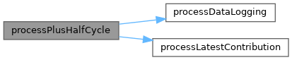
Process the start of a new positive half cycle for the specified phase.
This function is called just after the zero-crossing point of a positive half cycle. It processes the latest energy contribution, updates performance metrics, and handles data logging for phase 0.
- Parameters
-
phase The phase number [0..NO_OF_PHASES[.
- Processes the latest energy contribution for the specified phase.
- Updates the minimum number of ADC sample sets per mains cycle for phase 0.
- Handles data logging at the end of the logging period for phase 0.
- Resets cumulative power and sample count for the phase.
Definition at line 957 of file processing.cpp.

◆ processPolarity()
|
inline |
Processes the polarity of the current voltage sample for a specific phase.
This function removes the DC offset from the raw voltage sample and determines the polarity (positive or negative) of the sample. The polarity is stored for use in zero-crossing detection and other processing tasks.
- Parameters
-
phase The phase number [0..NO_OF_PHASES[. rawSample The current raw voltage sample for the specified phase.
- The DC offset is subtracted from the raw sample using a low-pass filter (LPF).
- The polarity is determined based on whether the filtered sample is greater than or less than zero.
Definition at line 405 of file processing.cpp.

◆ processRawSamples()
|
inline |
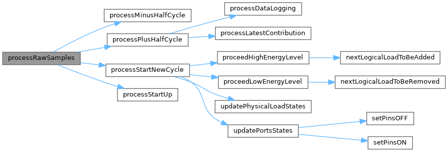
Processes raw voltage and current samples for the specified phase.
This routine is called by the ISR when a pair of voltage and current samples becomes available. It handles the processing of raw samples, including polarity detection, zero-crossing handling, and half-cycle processing.
- Parameters
-
phase The phase number [0..NO_OF_PHASES[.
- Determines the polarity of the current sample and handles transitions between positive and negative half cycles.
- Processes the start of new positive and negative half cycles.
- For phase 0, it triggers the start of a new mains cycle and handles startup logic.
Definition at line 995 of file processing.cpp.

◆ processStartNewCycle()
|
inline |
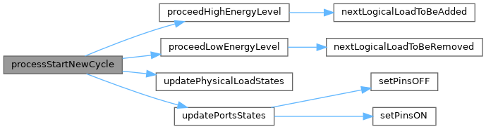
Processes the start of a new mains cycle on phase 0.
This function is executed once per 20ms (for 50Hz), shortly after the start of each new mains cycle on phase 0. It manages the energy level and load states, ensuring proper operation of the system.
- Handles recent transitions and updates the post-transition counter.
- Adjusts energy thresholds and determines whether to add or remove loads.
- Updates the physical load states and control ports.
- Ensures the energy bucket level remains within defined limits.
Definition at line 674 of file processing.cpp.

◆ processStartUp()
|
inline |
Processes the startup period for the router.
This function handles the initial startup period, allowing the DC-blocking filters to settle before normal operation begins. It ensures that the system is stable before processing energy and load states.
- Parameters
-
phase The phase number [0..NO_OF_PHASES[.
- During the startup period, the function waits until the filters have settled.
- Once the startup period is over, it resets key variables and flags to prepare for normal operation.
Definition at line 542 of file processing.cpp.

◆ processVoltage()
|
inline |
Processes the current voltage sample for the specified phase.
This function processes the voltage sample for a specific phase by calculating the cumulative voltage squared (V²) for RMS calculations, updating the low-pass filter for DC offset removal, and preparing for zero-crossing detection.
- Parameters
-
phase The phase number [0..NO_OF_PHASES[.
- The voltage squared (V²) is calculated and accumulated for RMS calculations.
- The low-pass filter is updated to remove the DC offset from the voltage signal.
- The polarity of the last confirmed sample is stored for zero-crossing detection.
- The number of samples during the current mains cycle is incremented.
Definition at line 503 of file processing.cpp.

◆ processVoltageRawSample()
| void processVoltageRawSample | ( | const uint8_t | phase, |
| const int16_t | rawSample ) |
Processes the current voltage raw sample for the specified phase.
This function processes the raw voltage sample for a specific phase by handling polarity detection, zero-crossing confirmation, and voltage processing. It ensures that the voltage sample is properly filtered and analyzed for further processing.
- Parameters
-
phase The phase number [0..NO_OF_PHASES[. rawSample The current raw voltage sample for the specified phase.
- Determines and confirms the polarity of the raw voltage sample.
- Handles zero-crossing detection and processes raw samples for the phase.
- Updates voltage-related metrics and increments the sample set count for phase 0.
Definition at line 1052 of file processing.cpp.

◆ updatePhysicalLoadStates()
|
inline |
Updates the physical load states based on logical load priorities and states.
This function maps the logical load states to the physical load states. It ensures that the physical loads are updated according to the logical priorities and states. The function also handles priority rotation if enabled.
The array, logicalLoadState[], contains the on/off state of all logical loads, with element 0 being for the one with the highest priority. The array, physicalLoadState[], contains the on/off state of all physical loads.
The lowest 7 bits of element is the load number as defined in 'physicalLoadState'. The highest bit of each 'loadPrioritiesAndState' determines if the load is ON or OFF. The order of each element in 'loadPrioritiesAndState' determines the load priority. 'loadPrioritiesAndState[i] & loadStateMask' will extract the load number at position 'i' 'loadPrioritiesAndState[i] & loadStateOnBit' will extract the load state at position 'i'
Any other mapping relationships could be configured here.
- Note
- This function is called during each cycle to ensure the physical load states are synchronized with the logical load states.
Definition at line 353 of file processing.cpp.

◆ updatePortsStates()
|
inline |
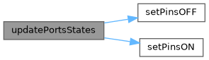
Updates the control ports for each of the physical loads.
This function determines the ON/OFF state of each physical load and updates the corresponding control ports. It applies override bitmask directly to force specific pins ON when override pins are active.
- If a load is OFF, its corresponding pin is added to the
pinsOFFmask. - If a load is ON, its corresponding pin is added to the
pinsONmask. - Override bitmask is applied directly to
pinsONfor immediate pin activation. - Finally, the pins are updated using
setPinsOFFandsetPinsONfunctions.
Definition at line 298 of file processing.cpp.

Generated by